|
|
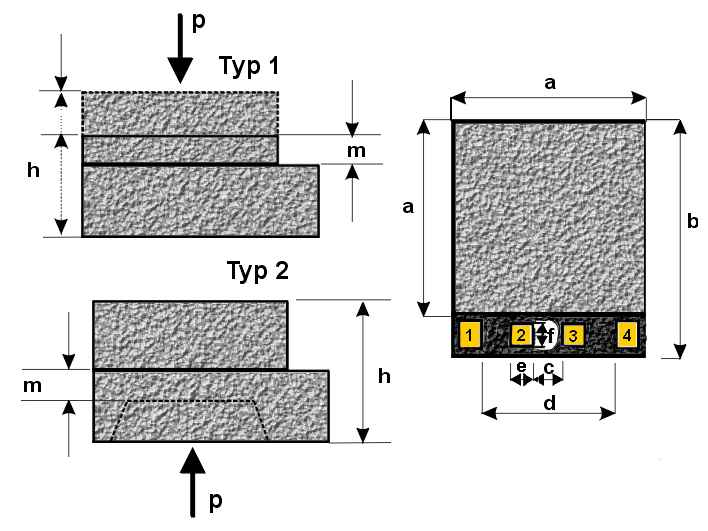
a =
4,32 mm b = 5,08
mm c = 0,76 mm d = 3,12 mm e = 0,50 mm f = 0,50 mm Type 1 : h = 0,75 mm ..... 1,50 mm m = 100 µm ..... 650 µm Type 2 : h = 1,35 mm ..... 1,50 mm m = 20 µm ..... 650 µm |
Technical Data
| Basic Sensor Architecture |
|
|
a =
4,32 mm b = 5,08
mm c = 0,76 mm d = 3,12 mm e = 0,50 mm f = 0,50 mm Type 1 : h = 0,75 mm ..... 1,50 mm m = 100 µm ..... 650 µm Type 2 : h = 1,35 mm ..... 1,50 mm m = 20 µm ..... 650 µm |
|
Type
1: The Membrane is on connection side. Total sensor thickness varies, depending on measurement range due to the membrane thickness which ranges from 100 µm to 650 µm. |
Type
2: The membrane is etched in the base wafer, therefore the total sensor height is independent of the measurement range or the thickness of the membrane. |
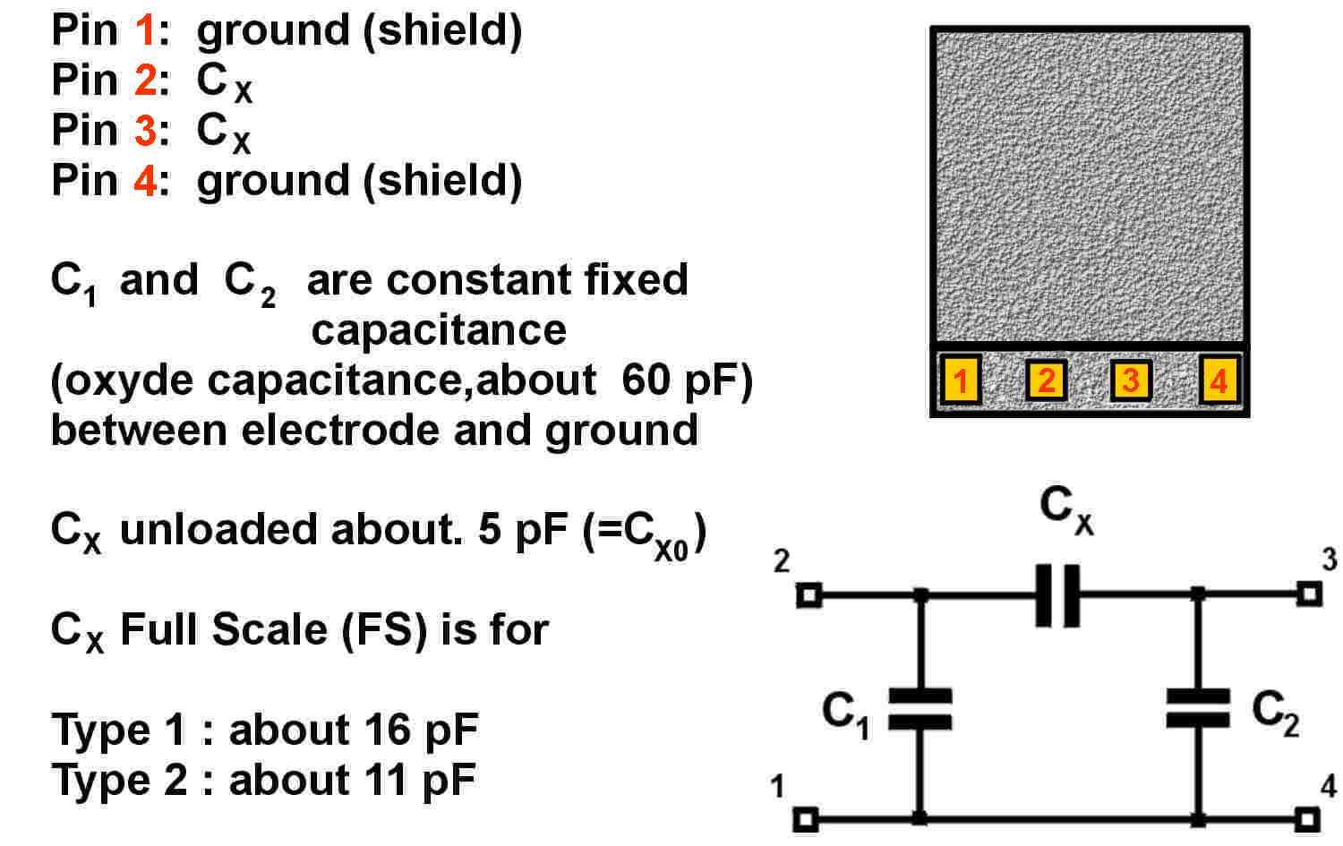
| Circuit Diagram - Chip Connections - Definitions |
 |
| Characteristic Curve |
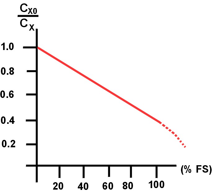 |
The
diagram shows the relation between the load (pressure or force) in % FS* and the sensor output Capacitance Cx * FS : (Full Scale) |
|
Temperature
drift of the zero point related |
|
Force - sensors
Pressure - sensors
· operational
temperature range
for sensors : up to +350°C, max. |
|||||||||||||||||||||||||||||||||||||||||||||||||||||||||||||||||||||||||||||||||||||||||||||
| Sensors´ drawing list |
Pressure-Sensors |
Force-Sensors |
|
| * optional: SS base plate thicknesses less then 0,18 inch (4.5 mm) available upon request |
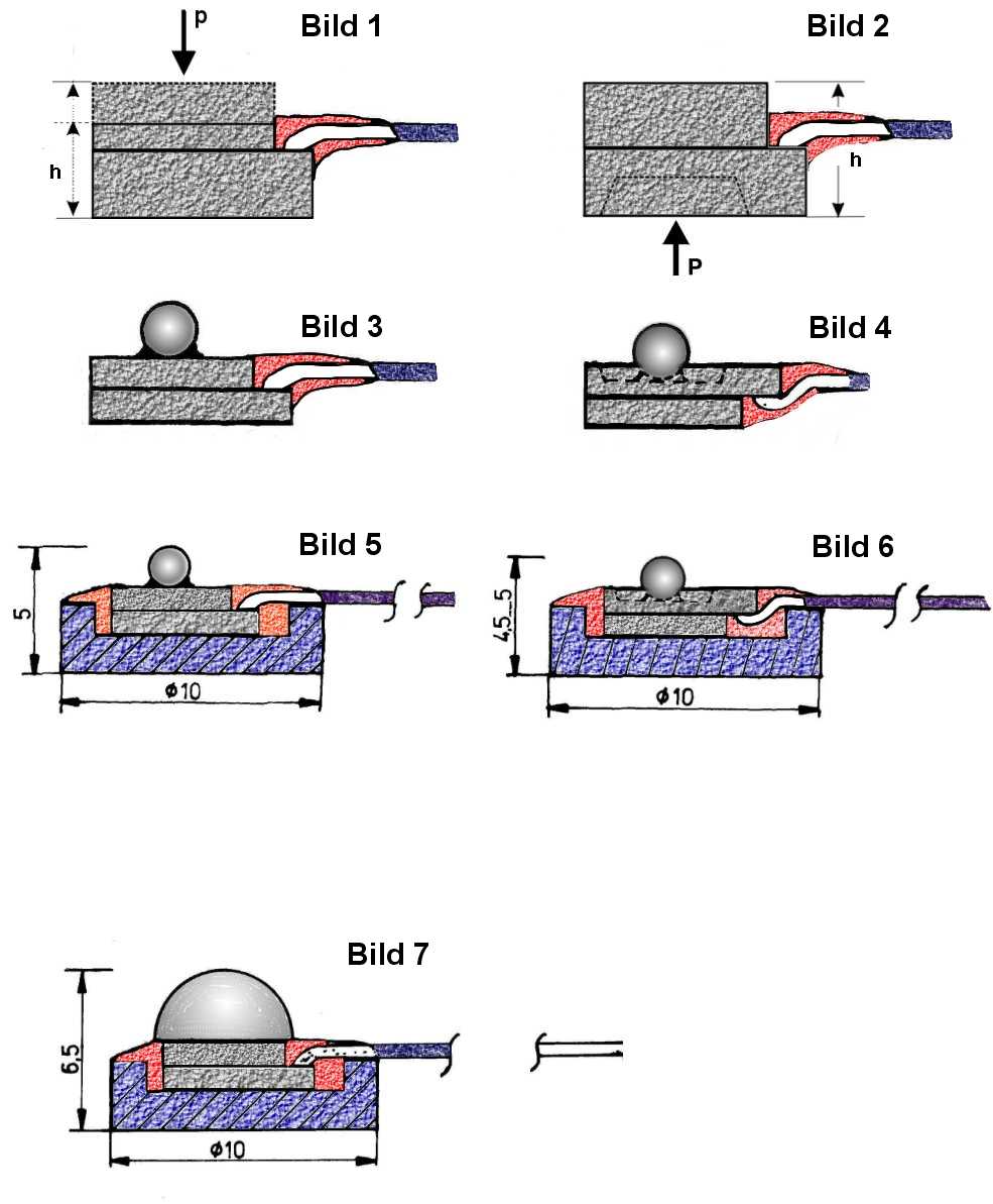
| Sensor drawings |
 |